TV Adaptor: U-TV0.5XC-3
|
Instructions for the Low-Magnification C-Mount Adapter U-TV0.5XC-3 |
|
|
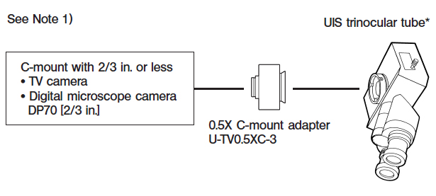
The U-TV0.5XC-3 is low-magnification TV adapter with C-mount which allows a digital imaging device such as a digital TV, EXCCD, UHCCD, UCMOS camera to capture wide-angle images. Use of telecentric optics helps reduce the occurrence of light deficiency in the peripheral sections. In addition, the transmittance at the infrared frequency band is extended to 1,000 nm. |
|
|
System Diagram |
|
|
|
|
|
* Can be used with an attachment having the same mounting structure as the UIS trinocular tube and straight photo tube.(U-TR30-2, U-TR30NIR, U-SWTR-3, U-DPT (port B), U-MPH, etc.) Note 1) Restrictions on the TV camera ·TV camera cannot be used if its C-mount surface is located below the camera surface. ·TV camera may get in the way of the microscope operation if the camera’s lateral size from the light axis exceeds 68 mm. ·When a TV camera having a larger CCDor CCD than specified is used, the image may lack brightness in the peripheral sections or a part of an image may be cut off. ·When the TV camera has high sensitivity or is not provided with automatic light control, the displayer image may become whitish. Should this happen, lower the light intensity level of the microscope. |
|
|
Assembly |
|
|
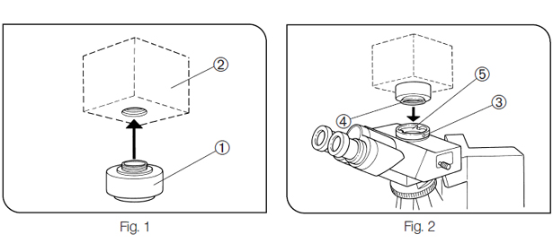
1. Attach the C-mount adapter 1to the C-mount TV camera 2 by screwing firmly. (Fig. 1) 2. Using the Allen screw driver provided with the microscope, loosen the straight photo tube clamping screw 3, then fit the mount dovetail 4 of the C-mount adapter into the straight photo tube mount 5 of the trinocular tube. (Fig. 2)(#For convenient parfocality adjustment, set the C-mount adapter so that the LOCK and FOCUS screws face sideways.) 3. Tighten the clamping screw 3 firmly. (Fig. 2) |
|
|
|
|
|
Operation |
|
|
Adjusting the Microscope |
|
|
1. Turn on the microscope light source and adjust the required points of the microscope to make it ready for observation. 2. Set the light path of the UIS trinocular tube to the TV light path. |
|
|
Adjusting the TV Camera and Displayer |
|
|
Perform the adjustments such as color adjustment by referring to the instruction manuals of your TV camera and displayer.(#The center of eyepiece and that of the displayer may not coincide correctly. This is a function of the CCD adjustment mechanism of the TV camera, not a malfunction) |
|
|
Adjusting the Parfocality Between the Observed Image and Displayed Image (Fig. 3) |
|
|
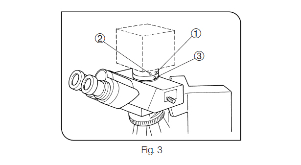
The parfocality adjustment requires the Allen wrench (for locking) providedwith the adapter and the Allen screw driver (for focusing) provided with the microscope. (#The parfocality adjustment range is ±0.8 mm. If the adjustment of the adapter is not enough, please also adjust the focusing feature ofthe TV camera.If the correct parfocality cannot still be obtained, use another TV camera) 1. Look into the eyepiece and bring the specimen into focus. 2. Set the TV light path and switch to the displayer image. 3. Loosen the parfocality adjustment screw (LOCK) 1 using the Allen wrench. 4. While observing the displayer image, adjust focus by turning the parfocalityadjustment screw (FOCUS) 2 slowly using the Allen screw driver. 5. When correct focusing is obtained, hold the FOCUS screw position by keeping the Allen screw driver inserted into it, and tighten the LOCK screw1 using the Allen wrench. |
|
|
|
|
|
Rotating the Camera (Fig. 3) |
|
|
Loosen the straight photo tube clamping screw 3. Rotate the TV camera and tighten the straight photo tube clamping screw3 firmly. |
|
|
Imaging Field Areas |
|
|
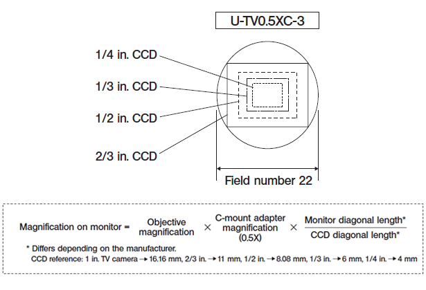
The following diagrams show the imaging field areas, which are determined by the field of view of the eyepiece (fieldnumber 22) and the size of the CCD seen through the C-mount adapter. |
|
|
|
|